Contents of this page are obsolete. This page is preserved and stored at this URL just from historical viewpoint. Original URL was http://www.mm.media.kyoto-u.ac.jp/members/kameda/...
Please visit www.kameda-lab.org for recent information. (2002/12/06, kameda@ieee.org)

UTP Cable

[Japanese] / Documents, Kameda, Minoh Lab 2000/07/04
I noticed that this page is sometimes refered from foreign countries (why?), so now I prepare this English page... (2000/06/27)
I tried to write correct instruction, but please hold yourself responsible for using information of this page.
An UTP cable (category 5) is one of the most popular LAN cables. This cable consists of 4 twisted pairs of metal wires (that means there are 8 wires in the cable). Adding RJ45 connectors at both ends of the UTP cable, it comes a LAN cable they usually use.

In Minoh lab, we always make UTP based LAN cables with the following instruction written by me. I don't know the instruction is formal or not, but at least it works well in Minoh lab.
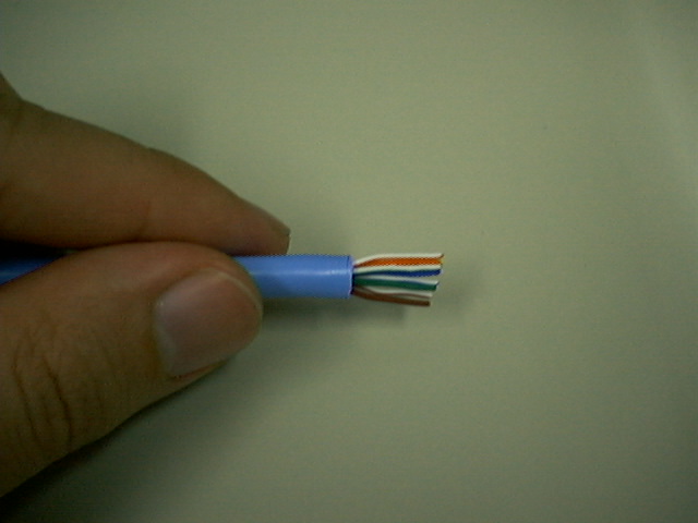
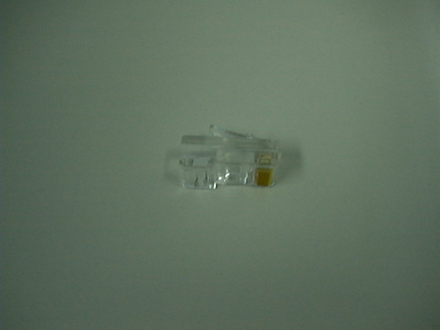
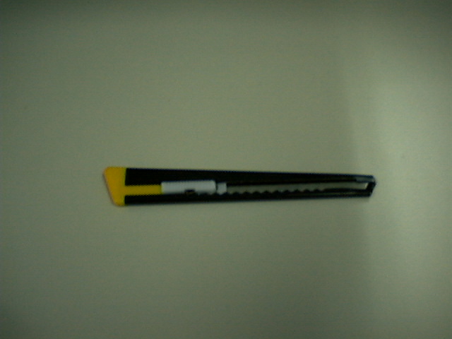
  1. 10 (100) Base T Straight
  2. 10 (100) Base T Cross
  3. ATM (155Mbps/25Mbps compatible) Straight
  4. ATM (155Mbps/25Mbps compatible) Cross
  5. CDDI Straight
  6. CDDI Cross
  7. ISDN S/T point connection

Preparation

You need a special plier, RJ45 connectors, UTP cables, and a cutter.
UTP Category 5 cable RJ45 Connector Special Plier Cutter

Making Cable

Follow the steps below.
  1. Remove the outmost vinyl shield for 12mm at one end of the cable (we call this side A-side).
  2. Arrange the metal wires in parallel (refer the each section's wire arrangement table). Don't remove the shiled of each metal line.
  3. Insert the metal wires into RJ45 connector on keeping the metal wire arrangement.
  4. Set the RJ45 connector (with the cable) on the plier, and squeeze it tightly.
  5. Make the other side of the cable (we call this side B-side) in the same way.
  6. After you made it, you don't need to take care of the direction of the cable. (Any cable in this page is directionless --- that means you can set either end of the cable to either device.)
How to see the wire arrangement
Take the UTP cable with your left hand and a RJ45 connector with your righyt hand. Hold the RJ45 connector in the way you can see the contact metal face (the horn(?) of the RJ45 connector comes invisible from you now). At this moment, I call Pin-number 1, 2, 3, ... from the upper side to the bottom side. This is the same at both side of the cable.
There are several different color set of UTP cables, so if the cable you have is not same as the one below, please re-map the color in a good way...

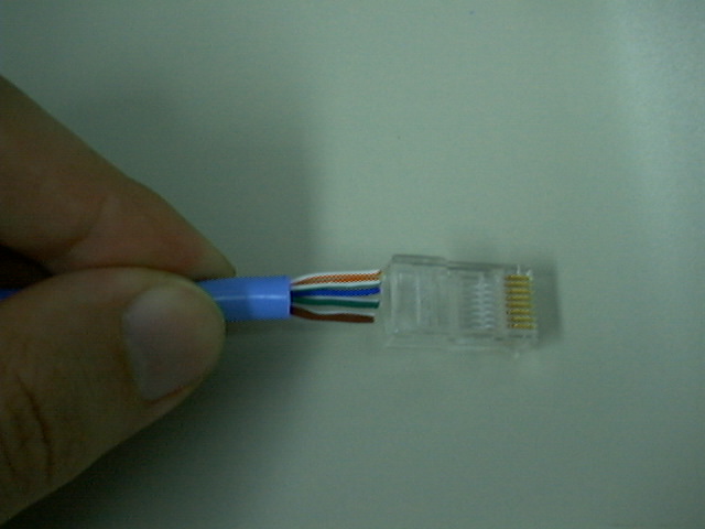
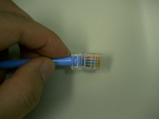
Same order in the wire arrangement table Insertion

The tables below are for the case where the UTP cable consists of green/green-white, orange/orange-white, blue/blue-white, brown/brown-white twisted pairs.


10 Base T / 100 Base T Straight

10BaseT and 100BaseT are most common mode of LAN. You can use UTP category-5 cable for both mode. (You can use UTP category-3 cable for 10BaseT, in which there are only 3 wires inside the cable.)
A straight cable is used to connect a computer to a hub. You can use it to connect 2 hubs in the case one of the hub has an uplink port (and you use normal port on the other hub).
Pin ID side A side B
1 orange-white orange-white
2 orange orange
3 green-white green-white
4 blue blue
5 blue-white blue-white
6 green green
7 brown-white brown-white
8 brown brown

10 Base T / 100 Base T Cross

A cross cable for 10BaseT and 100BaseT is used to connect 2 computers directly (with ONLY the UTP cable). It is also used when you connect 2 hubs with a normal port on both hubs. (In other words, the cross cable is used relatively in a rare case.)
Pin ID side A side B
1 orange-white green-white
2 orange green
3 green-white orange-white
4 blue blue
5 blue-white blue-white
6 green orange
7 brown-white brown-white
8 brown brown

ATM Straight

ATM straight cable is used to connect ATM NIC-card (computer) to ATM-Switch.

You can use the straight cable for 10BaseT and 100BaseT as ATM straight cable because the pin arrangement is the same. (Actually, an ATM straight cable uses only 1,2,7,8 pins in 155Mbps mode, and 3,4,5,6 pins in 25Mbps mode. However, the straight cable of 10BaseT and 100BaseT is fully wired and so there is no problem.)


ATM Cross

You use ATM cross cable to connect 2 ATM-Switches (Wow, you have two!) with normal ports. (If there is an up-link port on one ATM switch, I guess you can use ATM straight cable to connect 2 ATM-Switches. However, I have never seen an ATM-Switch which has an up-link port.)

An ATM cross cable uses only 1,2,7,8 pins in 155Mbps mode, and 3,4,5,6 pins in 25Mbps mode.

Concerning CDDI cross cable, the pin arrangement of 1,2,7,8 pins are same as that of ATM cross cable, so you can divert CDDI cross cable for 155Mbps ATM cross cable (though I don't think you have it...)
Pin ID side A side B
1 orange-white brown-white
2 orange brown
3 green-white blue
4 blue green-white
5 blue-white green
6 green blue-white
7 brown-white orange-white
8 brown orange


CDDI Straight

CDDI straight cable is used to connect CDDI NIC-card (computer) to CDDI concentrator. This cable is exactly same as the 10/100BaseT straight cable .

CDDI Cross

CDDIのクロスケーブルは、以下のピンアサインになります。
Pin ID side A side B
1 orange brown
2 orange-white brown-white
3 green green
4 blue blue
5 blue-white blue-white
6 green-white green-white
7 brown orange
8 brown-white orange-white

ISDN S/T point connection cable

ISDN S/T point connection cable is used to connect ISDN device (TA, digital telephone, etc) to an DSU. Actually, this is same as 10BaseT/100BaseT straight cable.
kameda@media.kyoto-u.ac.jp